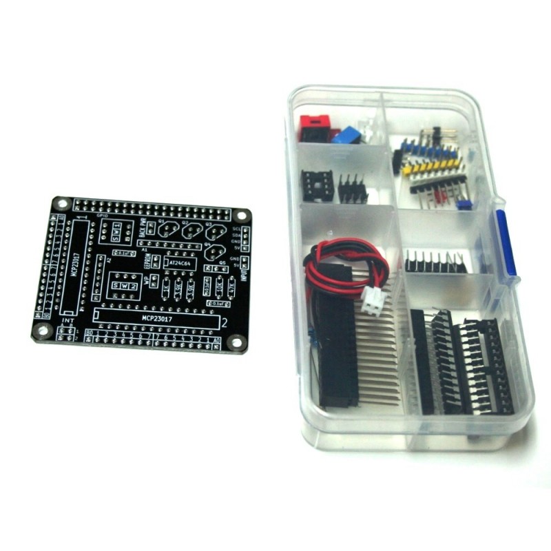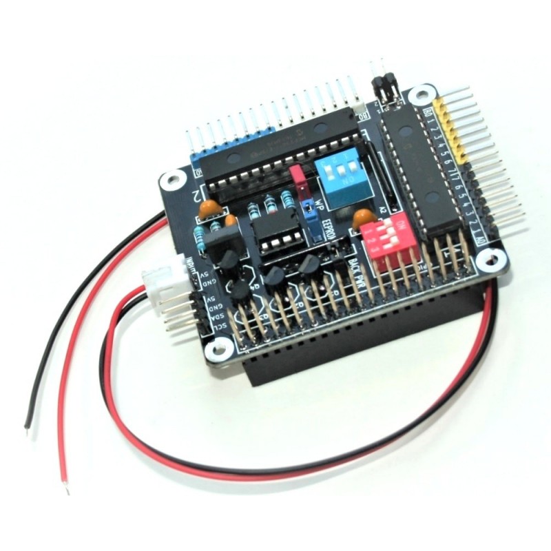

The Raspberry Pi HAT - 32 I/O Port Expander Kit Edition (RPI-32IO-PEBK) is a 32 Input/Output digital expansion board designed for use on the Raspberry Pi A+, Raspberry Pi B+, Raspberry Pi 2 Model B, Raspberry Pi 3 Model A, Raspberry Pi 3 Model B, and Raspberry Pi 4 Model B. This is a kit edition, in order to solder it, you only need a soldering iron and tin/lead solder wires.
Recommendations for the assembly of the board
https://www.nationelectronics.com/content/12-kit
The board use two Microchip MCP23017 16-bit I/O expander, allowing you to connect up to 32 digital inputs or outputs to the Raspberry Pi. The RPI-32IO-PEBK is connected to Raspberry Pi using a 20x2 GPIO connector with extended pins that allow you to stack many extension boards in a single Raspberry Pi.
You can select the I2C address using the on-board 3bits switches (ON=0 the pin is grounded, OFF=1 the pin is pull up to 5V). The MCP23017 supports up to 8 different I2C addresses as follow:


Due to there are two MCP23017 per board you are allowed to stack up to four RPI-32IO-PEBK boards on a single Raspberry Pi for a maximum of 128 I/O ports.
The right angle headers allow you to connect the I/Os while the boards are stacked.
The RPI-32IO-PEBK may be powered thru a 5V input polarized male connector (female cable to connect external supply included) or thru the Raspberry Pi GPIO 5V pins.
If you use the first option you can power the Raspberry Pi shorting the "Back PWR" jumper or isolate the Pi and RPI-32IO-PEBK keeping it open. In order to power the RPI-32IO-PEBK thru the Raspberry Pi GPIO 5V pins the "Back PWR" jumper must be shorted.
Use of an external supply is recommended when you connect more than one RPI-32IO-PEBK boards to your Raspberry Pi.
Specifications
Vdd (5V polarized input header without BACK PWR): 4.5V - 5.5V
All digital inputs and outputs: 0 - Vdd
Maximum current on a single I/O Pin (sourced or sunk): 25 mA
Maximum current on each MCP23017 chip: 125 mA
Features
- 32 Digital Inputs/Outputs
- Based on the Microchip MCP23017 chip
- Control via the Raspberry Pi I2C port
- Selectable I2C addresses thru switches
- Stackable, up to 4 boards per Raspberry Pi
- Right angled headers for ease connection when stacked
- All I/Os are 5V tolerant
- Built in 3.3V to 5V shifter for Raspberry Pi I2C port protection
- Powered thru a 5V polarized input header from an external supply
- Raspberry Pi can be Back Powered or isolated thru a jumper
- The board can be powered thru the Raspberry Pi GPIO 5V pins
- Programmable AT24C64 EEPROM for Raspberry Pi HAT compliant
- Right angled header for 5V tolerant I2C port (SCL and SDA)
Demo Codes and schematics
You can download all of the libraries and schematics from github at:
https://github.com/nationelectronics/
To download the C libraries to your Raspberry Pi type in terminal:
git clone https://github.com/nationelectronics/nationelectronics_C_libraries.git
To download the schematics:
git clone https://github.com/nationelectronics/nationelectronics_schematics.git
Recommendations for the assembly of the board
https://www.nationelectronics.com/content/12-kit
Purchase options
You can buy this item here:
or at Amazon:
https://www.amazon.com/dp/B01N27A7TT
Other resources
Electronics Primer: How to Solder Electronic Components
Enabling The I2C Interface On The Raspberry Pi
Interfacing an I2C GPIO expander (MCP23017) to the Raspberry Pi using C++
Wikipedia I2C (Inter-Integrated Circuit)
MCP230xx GPIO Expander on the Raspberry Pi
How To Use A MCP23017 I2C Port Expander With The Raspberry Pi – Part 1
