Raspberry Pi HAT - 32 I/O Port Expander - MCP23017 - I2C - Kit Edition
For support click here:
http://www.nationelectronics.com/content/10-support-32io-kit
It is recommended to weld the board in the following order:
| 1 | PCB | 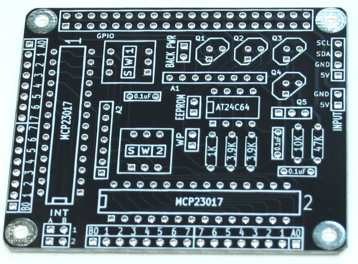 |
All the components must be welded in the back side of the PCB, except the 2x20 pins connector. |
| 2 | 2x20 pins connector | 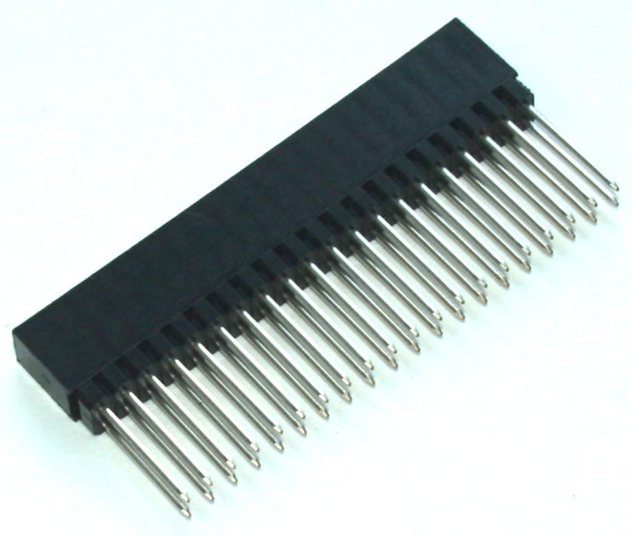 |
The 2x20 pins connector must be welded in the front side of the PCB. |
| 3 | Connectors | 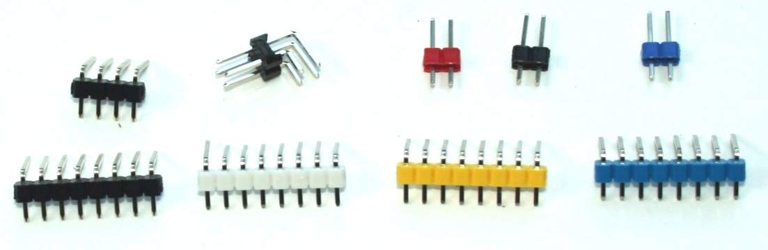 |
|
| 4 | IC Sockets | 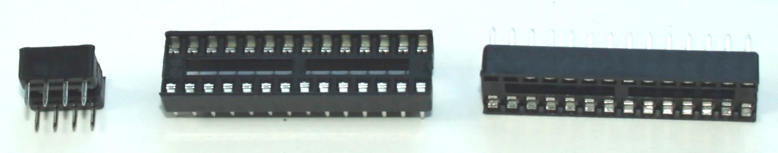 |
The rounded edge must be toward the square hole in the PCB
|
| 5 | 2 pins polarized connector | 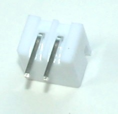 |
|
| 6 | 3 bits switches | 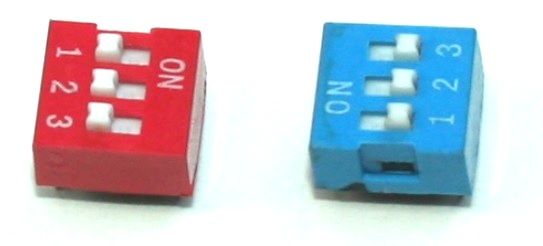 |
Pin No. 1 (under the number "1") must match the square hole in the PCB
|
| 7 | 8 pins array resistor B type | 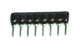 |
|
| 8 | 7 pins array resistor A type | 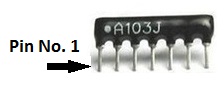 |
Pin No. 1 must match the square hole in the PCB
|
| 9 | Resistors | 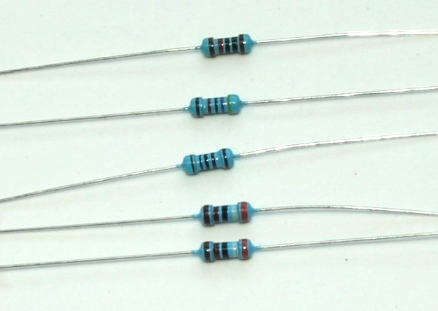 |
|
| 10 | Capacitors | 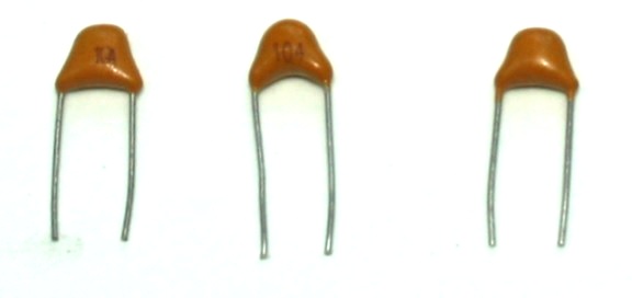 |
3 x 0.1uF capacitors --> "0.1uF" |
| 11 | Transistors | 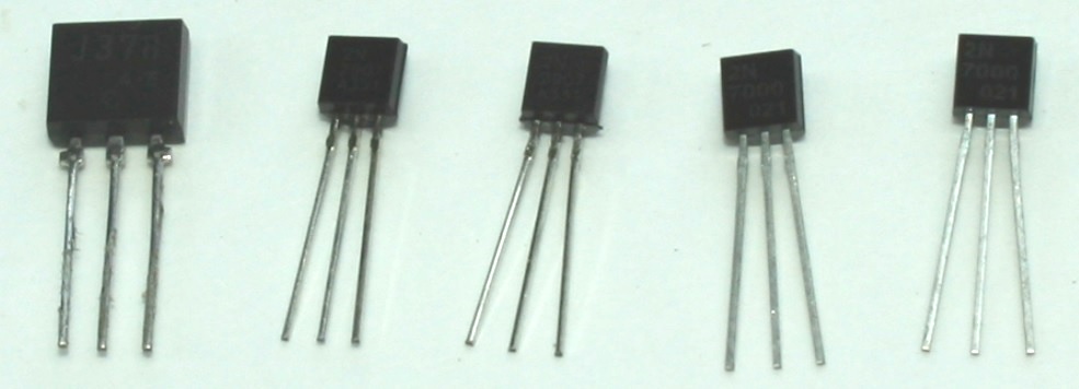 |
The pins No. 1 are allways at left, when you are reading the letters on transistors. Pin No. 1 must match the square hole in the PCB.
|
| 12 | Chips | 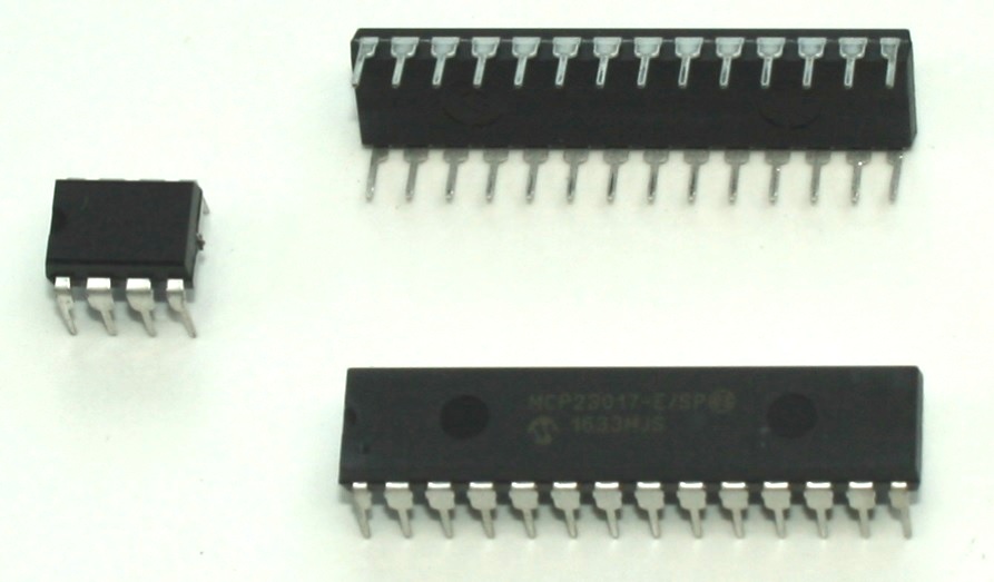 |
Insert carefully the chips into the sockets, the pin No. 1 of the chip must be toward the rounded edge of the socket.
|
| 13 | Jumpers | 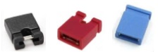 |
Insert the jumper's caps
|
| 14 | Board finished | 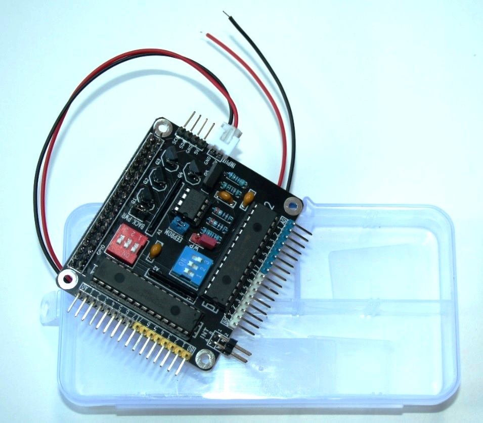 |
Work complete! |
Other resources: